Resistance Boxes & DBR for EOT Cranes
Punched Grid.
Current Rating - 10 Amps to 800 Amps.
Punched Grid Resistance Boxes are designed from the ground up for harsh Industrial Use.
Two Different models are available
Stainless Steel wire grid resistors
Punched Steel Grid Resistors.
EOT Crane Resistance Box & DBR Description:
Resistors are supplied for both AC & DC Requirements. The basic types of resistors are stainless steel wire & punched steel.Suitable for current rating 10 to 800 Amps.Multiple paths are used for system having higher ratings.
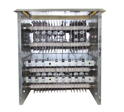
Punched Steel Grid Resistors for EOT Cranes
Punched Steel Grid Resistors consist of grids punched from sheet of corrosion resistant nickel chromium alloy sheet steels.The punched steel grids are very robust with no effect ofjerks,shocks or vibrations.Ideal for heavy duty oeprating conditions like steel mill application.Avalable in current rating 8 Amps to 800 Amps.
Product List of Resistance
| Sr. no. | Product Name | Description | Part Number | Images |
|---|---|---|---|---|
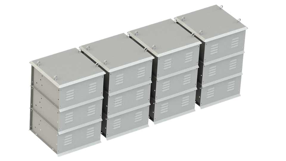
| 1 | RESISTANCE BOX & DBR (S.S. PUNCHED GRID TYPE) | SS Punched Grid Type Resistance Box & DBR with RA: RV: Steps: | RESISTANCE BOX & DBR (S.S. PUNCHED GRID TYPE) | |
| 2 | DYNAMIC BREAKING RESISTANCE (DBR PUNCHED GRID TYPE) | DYNAMIC BREAKING RESISTANCE (DBR PUNCHED GRID TYPE) | RESISTANCE BOX & DBR (S.S. PUNCHED GRID TYPE) |
Applications of Crane Resistance Box & DBR
EOT Cranes
Electric Hoists
Gantry Cranes
Goliath Cranes
Mobile Cranes
Tower Cranes


Punched Grid Resistance Box & DBR Technical Data Specifications
|
|
||
| Enclosure | Sheet Steel Duty galvanized/Painted. | |
| Mounting Position | Floor | |
| Protection Degree | IP-11/IP-21/IP-23/IP-33 | |
| Current Rating(S.S grid) Continuous | 7-400 Amps | |
| Current Rating(S.S grid) Continuous | 7-800 Amps | |
| Cooling | Air/Oil Cooled | |
| Temperature Rise | 2250C/2500C/3750C | |
| Cable Entry | Bottom |
Current Rating for various Duty Factors(Amps)
| Rated Value Ohms | Grid Type | 25% ED | 40% ED | 60% ED | 100% ED |
|---|---|---|---|---|---|
| 0.010 | PS 10 | 390 | 325 | 280 | 234 |
| 0.022 | PS 22 | 265 | 220 | 190 | 158 |
| 0.032 | PS 32 | 220 | 182 | 153 | 131 |
| 0.046 | PS 46 | 185 | 151 | 130 | 110 |
| 0.068 | PS 68 | 152 | 126 | 110 | 90 |
| 0.100 | PS 100 | 125 | 103 | 88 | 74 |
| 0.150 | PS 150 | 101 | 84 | 72 | 61 |
| 0.220 | PS 220 | 83 | 70 | 59 | 50 |
| 0.300 | PS 300 | 82 | 59 | 50 | 43 |
| 0.460 | PS 460 | 58 | 48 | 40 | 35 |
| 0.720 | PS 720 | 47 | 39 | 33 | 28 |
| 1.000 | PS 1000 | 40 | 33 | 28 | 24 |
| 1.500 | PS 1500 | 32 | 27 | 23 | 19 |
| 2.500 | PS 2500 | 25 | 21 | 18 | 15 |
| 4.500 | PS 4500 | 15 | 13 | 11 | 8 |
The Resistance Box & DBR for EOT Cranes: How they Operate and Optimize Slip Ring Motors
Introduction
Resistance boxes & DBR play a critical role in the efficient and safe operation of Electric Overhead Traveling (EOT) cranes. By providing control over slip ring motors, resistance boxes enable seamless lifting and moving of heavy loads. In this comprehensive guide, we will explore how resistance boxes & DBR are built, how they operate slip ring motors, and the factors to consider when designing them based on rotor voltage, rotor amps, and the number of steps.
How Resistance Boxes are Built
Resistance boxes for EOT cranes are meticulously crafted to meet stringent operational requirements. They are designed to withstand high electrical current and harsh working conditions, ensuring reliable and long-lasting performance. Here's a breakdown of their construction process:
1. Quality Materials: Resistance boxes are typically fabricated using high-grade materials such as stainless steel or aluminum, offering excellent durability and resistance to corrosion.
2. Sturdy Enclosure: The box is encased in a robust and weather-resistant enclosure, protecting the internal components from external elements, such as dust and moisture.
3. Precision Wiring: The internal wiring is meticulously installed, following industry and safety standards, to ensure optimal conductivity and minimize electrical disturbances.
4. Variable Resistance: Resistance boxes incorporate multiple resistance steps that can be adjusted to control the speed and torque of the crane motors, enhancing precision and operational versatility.
How Resistance Boxes Operate Slip Ring Motors
Resistance boxes act as variable resistance controllers, connecting in series with the rotor windings of slip ring motors to regulate their torque and speed. When the crane is in operation, the resistance box consistently adjusts the amount of resistance in the circuit, allowing the gradual acceleration of the motor. Here's a closer look at how resistance boxes operate slip ring motors:
1. Rotor Voltage Control: By adjusting the resistance steps, the resistance box regulates the voltage supplied to the slip ring motor's rotor windings. This control optimizes motor performance, ensuring smooth acceleration and deceleration.
2. Rotor Amps Management: Resistance boxes also play a crucial role in managing the rotor amps, preventing excessive current flow that could damage the motor or lead to safety hazards.
3. Smooth Speed Control: Gradual tapping of resistance steps enables controlled speed adjustments, minimizing the jolts and jerks during acceleration or deceleration phases of the crane operation.
Design Considerations: Rotor Voltage, Rotor Amps, and Number of Steps
When it comes to designing resistance boxes & DBR for EOT cranes, various factors must be considered to optimize performance. The rotor voltage, rotor amps, and the number of steps implemented in the resistance box & DBR heavily influence the efficiency and safety of the crane's operations. Here is an overview of these design considerations:
1. Rotor Voltage: The resistance box & DBR should be designed to accommodate the specific rotor voltage required by the slip ring motor. Adjusting the resistance steps accordingly ensures consistent and appropriate voltage delivery for optimal motor performance.
2. Rotor Amps: Based on the motor's power rating and operational requirements, the resistance box & DBR must be capable of efficiently managing the rotor amps. This prevents overheating and protects the motor and other components from potential damage.
3. Number of Steps: Incorporating the right number of resistance steps allows precise control over the motor's speed and torque. A greater number of steps offers a finer adjustment range, enabling smoother operation and reducing stress on the machinery.
FAQs
Q: Can I use a resistance box & DBR designed for other applications in EOT cranes?
A: It is recommended to use resistance boxes specifically designed for EOT cranes to ensure optimal functionality and safety. Dedicated resistance boxes & DBR are built to withstand the demanding conditions unique to crane operations.
Q: Are resistance boxes & DBR compatible with all types of slip ring motors?
A: Resistance boxes & DBR can generally be used with most slip ring motors, but it is important to verify compatibility and consider specific motor requirements during the design and selection process.
Conclusion
The resistance box & DBR for EOT cranes serves as a vital control component, enabling seamless operation and optimal performance of slip ring motors. By carefully considering rotor voltage, rotor amps, and the number of steps, engineers can design resistance boxes & DBR that ensure efficient, safe, and reliable crane operations. Understanding the construction, functionality, and design considerations of resistance boxes & DBR empowers professionals in the industrial sector to enhance their crane systems' performance effectively.
HOW SS Punched Grid Resistance Box & DBR Is Manufactured?
Manufacturing a Stainless Steel (SS) Punched Grid Resistance Box & DBR involves several steps and processes to create a high-quality and durable product. These resistance boxes & DBR are commonly used in EOT Cranes, where precise resistance values are required for controlling the flow of current in the Slip Ring Motor. Here's a general overview of how they are manufactured:
Materials and Tools:
Stainless Steel Sheets: These sheets are cut and perforated to create the grid structure.
Metal Cutting and Perforation Equipment: Laser cutting or punching machines.
Welding Equipment: To assemble the resistance box.
Electrical Components: Terminals, wiring, and insulation materials.
Measuring Instruments: To ensure precise resistance values.
Manufacturing Steps:
Design and Planning:
The first step in manufacturing an SS punched grid resistance box & DBR is to design the box's layout and specifications. Engineers determine the required resistance values, dimensions, and grid pattern. The design should ensure efficient cooling and durability.
Cutting and Perforating Stainless Steel Sheets:
Stainless steel sheets are cut into the desired size and then perforated to create a grid pattern. Laser cutting or punching machines are used for precision.
Creating Resistance Elements:
Nichrome wire or another suitable resistance wire is carefully wound on the perforated grid pattern. The winding pattern and length are determined based on the required resistance value.
Assembly:
The SS Punched grids with different resistances are then assembled together to form the resistance box & DBR. The assembly points should be strong and secure to ensure electrical and mechanical integrity.
Terminal Connections:
Electrical terminals are attached to the resistance box & DBR, allowing for easy connection to the electrical circuit. The terminals should be securely welded or bolted to the box.
Quality Control:
Each resistance box & DBR is thoroughly tested to ensure that it meets the specified resistance values and performance standards. Precise measuring instruments are used to verify the resistance.
Insulation and Enclosure:
If required, insulation materials may be added to ensure safety and protect against electrical shock. The entire resistance box & DBR is often enclosed in a protective housing.
Labeling and Marking:
Resistance boxes & DBR are labeled with important information, such as resistance values, power ratings, and any safety instructions.
Final Inspection and Packaging:
The finished resistance boxes & DBR undergo a final inspection to check for any defects. Once they pass quality control, they are packaged for shipment or distribution.
It's essential to note that manufacturing an SS punched grid resistance box & DBR requires precision and quality control to ensure that the resistance values are accurate, and the product is reliable and safe for use in electrical circuits. Additionally, the design and manufacturing processes may vary depending on the specific requirements and standards of the application or industry in which the resistance box will be used.